This Hardware challenge was one of the most fun challenges I have done. I had just learned some hardware stuff at school some time back, and this was the perfect time to put that into practice. The best challenges are ones where once you see it, everything just clicks right into place, and this was a great example of that. We'll learn about understanding circuit diagrams and we'll decode a signal accordingly.
The Challenge
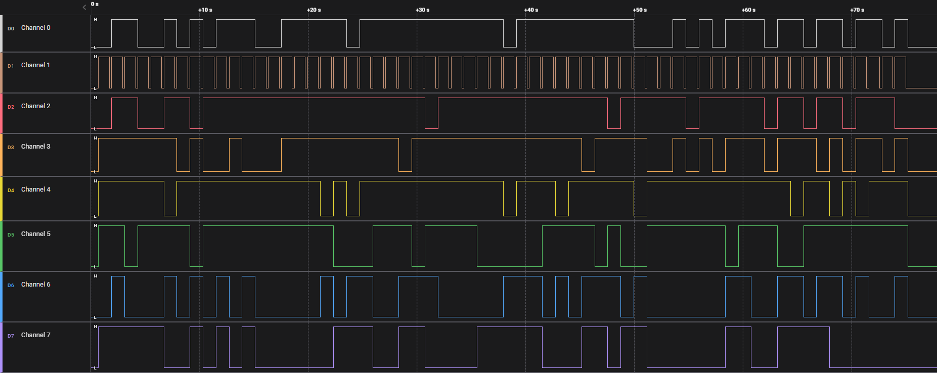
There were a few different files contained in this challenge. First of all, a hw_secret_codes.sal file which I was somewhat familiar with. This .sal file is a file containing raw binary signals and can be viewed with the Saleae Logic 2 program. Opening it up will reveal 8 different channels with different signals:

All these signals look very random, except for Channel 1. It seems to be repeating up and shortly down every time another signal goes up or down, common for a Clock signal. But for understanding the rest of these channels, we'll have to look a little further.
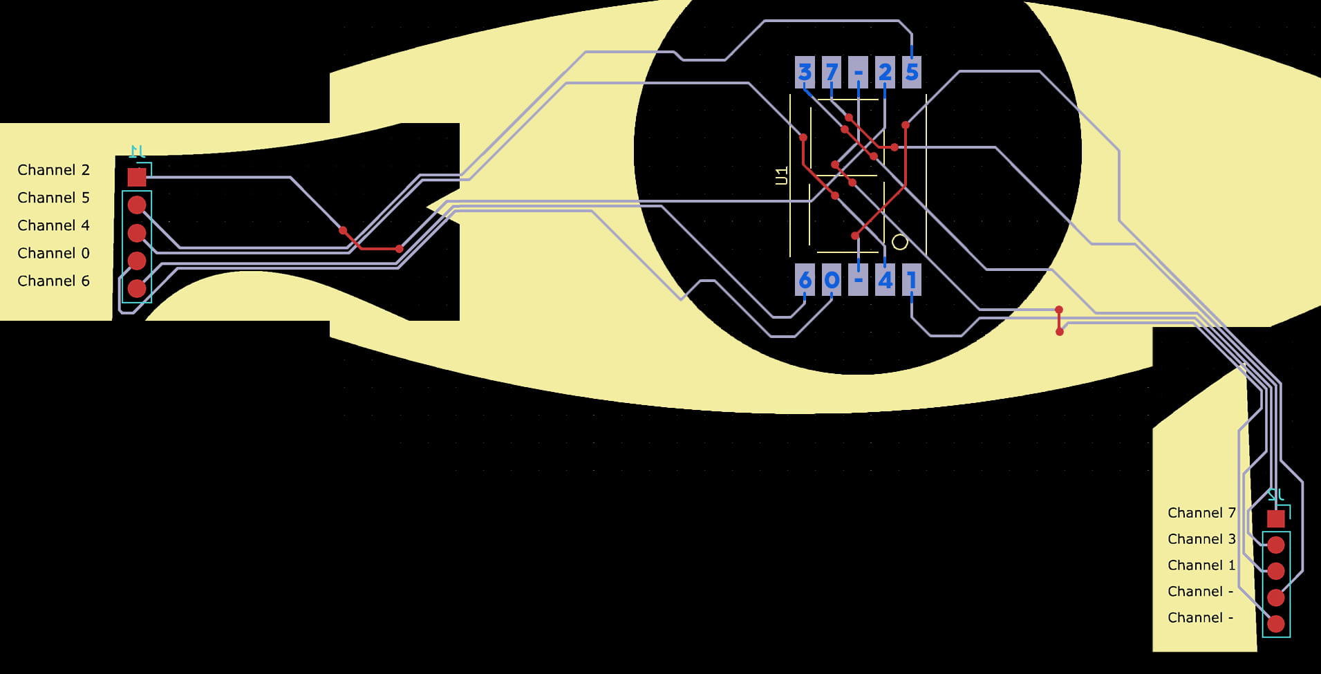
There were a few more files in the challenge, nine different .gbr files, and one .gbrjob file. Searching online for this file extension reveals these are 'Gerber' files, which can be viewed using several different programs, including KiCad. These files are schematics for PCB plates that show how all the physical hardware connects. We can view it in the software to see all the connections:

Here I have followed and marked in blue where the channels connect to on the center part. This will come in useful later.
Just looking at this diagram, it's still pretty confusing. All the wires seemingly just end at this rectangle, and it feels like they should somehow connect...
Understanding the Channels
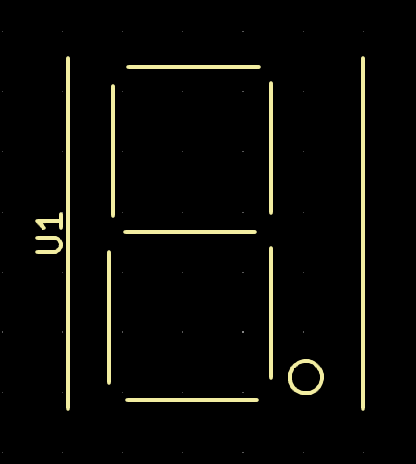
In a previous challenge, we learned that you can peel off layers from the Gerber file to view things behind, or isolate layers. There is a big mess of connections in the center part, so let's see what is behind there more clearly:

Aha! That's where it clicked. This is a 7-segment display, that they use for alarm clocks and things to display numbers easily with hardware. The 'rectangles' are pins on this display, and the channels connect to those pins via the wires!
The numbered channels from 0-7 likely correspond with the channels in Saleae Logic 2, meaning these signals will display certain lines on the display together creating characters. These change over time and can display a message in that way. We just need to figure out how this display connects exactly to be able to recreate it and simulate what would have been displayed with the signals we have.
Simulating the Display
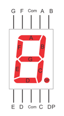
Searching around online for any 7-segment displays that have 5 pins at the top, and 5 pins at the bottom quickly results in a diagram like the following:

It works pretty simply. Each pin on the display corresponds to a line as part of the 7 segments. Except for three different pins: the two Com labeled pins, used for powering the display, as well as the DP pin which is the Decimal Point. These match perfectly with our case as here too, the middle two pins are connected to the - channels in Gerber Viewer, and the special dot lines up with our Channel 1, the 'clock' signal.
Now we know which lines on the display correspond to which channel in the signals:
3 7 - 2 5
G F ? A B

E D ? C .
6 0 - 4 1
We just have to simulate these signals on what they would display. To start scripting with these signals we can export them from Logic 2 by going to File -> Export Data and saving all the channels as CSV for example. Then we can easily parse it in Python:
=
=
# [['0.000000000', '0', '0', '0', '0', '0', '0', '0', '0'], ['0.695667880', '0', '0', '0', '1', '0', '0', '0', '0'], ['0.695672280', '0', '0', '0', '1', '0', '0', '0', '1'] ...
From here, we need to convert these 1's and 0's to the right lines on a display. I made a simple function that displays it in ASCII art:
# Convert binary to line character
=
=
# A
# F, B
# G
# E, C
# D
# -
# |
# = 7
# |
We can already run the entire signal through this function to see some character-like output, but not all the ASCII art this prints looks like a valid character. This is because the Logic 2 export makes a row every time any of the channels change, so we get a sort of slow-motion view of how each separate line turns on or off.
To solve this, we can use the currently unused DP channel (Channel 1) to act as a clock, where every time this signal turns on, we display the current character. It will turn off while the next character is being built and then turned back on when it is ready to be displayed.
=
# 'clock'
We're really close now. The terminal shows all the characters in ASCII art form, but ideally, we would have it as text to copy. We can see that the only characters it ever displays are the numbers 0-9, and letters a-f, this is hex encoding! We just have to make a mapping of binary, to the character it represents. After some testing you might get a list like this:
=
Finally, we build up the string of decoded characters into a hex result, and decode it to get the flag:
=
=
# Clock
=
+=
Running all these parts together finally prints the flag, decoded from the signals!
HTB{p0w32_c0m35_f20m_w17h1n@!#}