Before this CTF, I had never done any hardware-related challenges. I did have a little experience with Arduino from school, so I thought why not give it a try. This was a great introductory challenge for hardware, and I learned a lot about how Arduino and the wire connections work.
Challenge
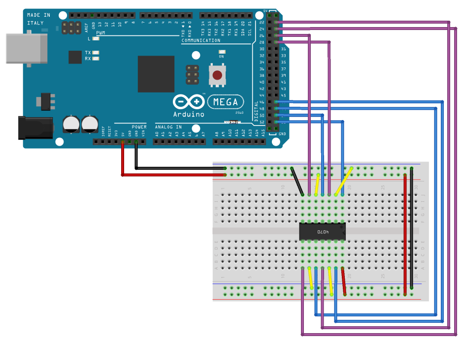
We were given an image of the circuit. It uses an Arduino board and a breadboard with quite a few wires and some sort of module in the middle.

We also got the Arduino source code for the challenge, which contained some code to set up the input and output pins, and some logic to print out the flag.
char * flag = "REDACTED";
String curr, first, second;
int in1=29, in2=27, in3=25, in4=23;
int out1=53, out2=51, out3=49, out4=47;
int i;
String
// Integer to binary string
String
void
void
The last loop() function is the most interesting because there is the logic of how the flag gets printed to the Serial output. Lastly, we also get this serial output in a file with lots of binary strings:
00110011
00111001
00110100
...
00110111
00110110
00101000
These binary strings are the output of the program, so we need to somehow reverse these back into the flag.
Analysing the code
Looking at the loop() function, we see that it just loops through every character of the flag. Then it converts the character value to binary and splits it into two strings, one with the first 4 bits, and one with the last 4 bits.
After that, it calls the get_output() function, on both of these strings. This function sets the bits from the binary string to high in the input pins and then waits a second. Finally, it reads the output pins and returns the binary string of the output. It basically puts the flag through the circuit and reads the output.
The Circuit
So our goal is now to understand what happens in the circuit, and how we can reverse the binary strings back into the flag. We can see a lot of wires going from the Arduino to the breadboard. If we follow the wires we can see that the pins are connected as follows:
GND  27  5V  51  29 GND  53
 │   │   │   │   │   │   │
┌┴───┴───┴───┴───┴───┴───┴┐
│           CHIP          │
└┬───┬───┬───┬───┬───┬───┬┘
 │   │   │   │   │   │   │
 25 GND  49  23  5V  47  5V
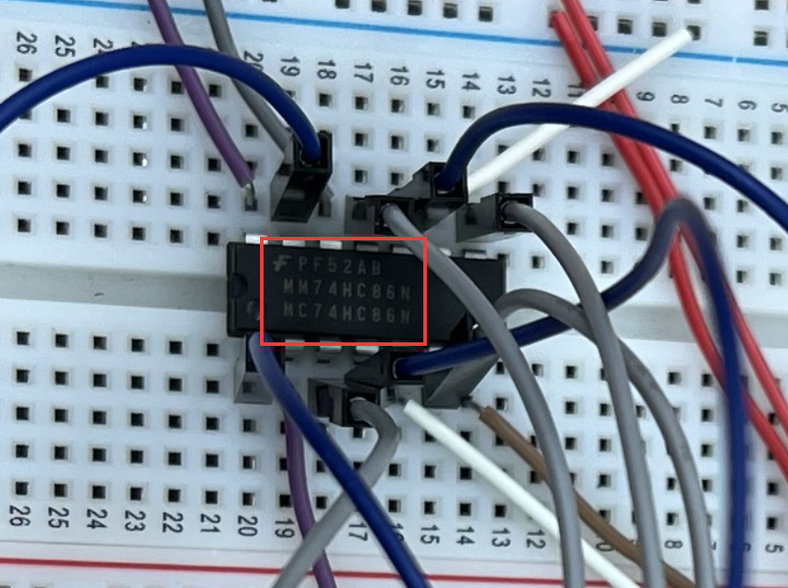
In the challenge, we also get another file, a photo of the setup in the real world. This is a very high-resolution image, and when we zoom in on the chip we can see the exact model:

We can read the following:
F PF52AB
MM74HC86H
MC74HC86N
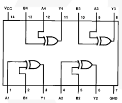
If we now search on Google for the MM74HC86H string, we get a datasheet of the exact model!

This datasheet shows all how all the connections go through the chip. It looks like it just XORs a few pins with each other.
Reversing the Circuit
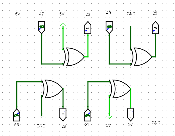
Now that we have the exact model of the chip, we can reverse its logic to get back the flag. To play around with this circuit I used a program I had also used for school called Logisim. The program allows you to build a circuit, and then test different inputs to see what comes out. So I built the circuit in the program:

We can see that it's all XOR operations with an input pin, then either 5V or GND and then the output pin as output. We can translate the XOR operation into basically just flipping the input pin if the other input (5V or GND) is on. And since 5V = ON, and GND = OFF, we can just flip the input pin whenever 5V is used.
With this logic, the only thing this really does is flip the bit if the input is pin 47 or 51. If we look back at the Arduino code on the following line we can see that these correspond to bits 1 and 3:
int out1=53, out2=51, out3=49, out4=47;
If we remember how the Arduino code worked from earlier, it just put the first 4 bits of the character through this circuit and the last 4 bits. Meaning we only have to flip these bits to get back the flag. Putting this in Python code looks something like this:
=
=
"""Flips bit with index from right to left"""
= -
= 1 # Flip bit
return + + # Start + flipped + end
=
=
return
= b
=
=
= +
+= # Decode from binary
This script flips the 1 and 3 bits from both parts and puts them back together to form the flag character by character. And at the end, prints the flag!
flag{a16b8027cf374b115f7c3e2f622d84bc}